
Ender 5 Dual Z Conversion
This exciting project converts my Creality Ender 5 3D printer to a dual Z-axis system, making prints more reliable and consistent across the entire buildplate.
This mod solves the issue of a sagging printbed caused by its original cantilever configuration. I was unsatisfied with all of the popular conversion kits and others' custom mods because they all limit print visibility and/or add to the overall volume of the printer. I knew I could do it better.
This project consisted of moving the Z axis from the back of the printer to the right and adding a second assembly on the left side, laser cutting custom plates to mount moving parts, 3D printing jigs to cut aluminum extrusions with a circular saw and drilling parts with a dremel, and rearranging the layout of most of the printer's components to make a good-looking, functional, and unique printer.
Overview of Features
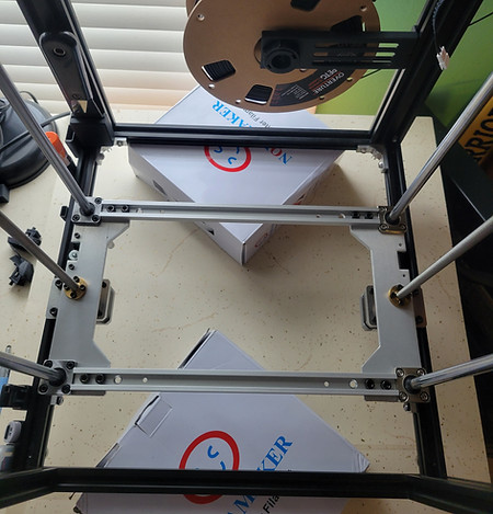
Left-Right Z Axes
Almost every available kit and custom mod I found simply added a second Z axis to the front of the printer. This makes sense since it's the simplest and least intrusive way to go. I think this looks bad.
I did some careful measuring and realized that if I added a 2020 rail on each side under the existing ones, shortened the linear rods and lead screw by 20mm, and mounted the upper rod brackets on them, I could fit the Z axis assembly on the sides without sacrificing build volume.
Lowered Front Crossbar

A big flaw to the Ender 5 design is the crossbar that goes across the front of the printer is level with the hotend, blocking the view of the nozzle when printing and bed leveling.
Many mods exist to combat this, most consisting of printing brackets to place the bar anywhere along the vertical front beams. This is a fine solution, but I wanted something with a cleaner look.
By making the crossbeam 40mm shorter, I could lower it between the vertical beams. I cut 20mm off each end of the beam, instead of 40mm off one side, so I could reuse the existing mounting holes.
This worked great and was actually doable since my Z axes were on the sides.
Manufacturing
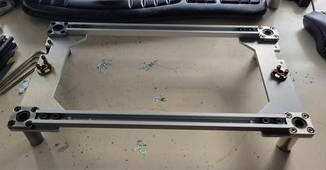
Laser Cutting
I designed new bearing plates, which mount to the linear bearings and lead screw, because I wanted different mounting holes for the build plate struts I would add, and I needed to change the Z stop mount due to lowering the height of the entire Z assembly.
I made these plates sleeker than the original, removing unnecessary material on the sides and aligning them with the edges of the linear bearing flanges.
I didn't have access to a laser cutter, so I had these parts laser cut from 5052 aluminum from a laser cutting service. I designed bolt holes to the appropriate diameters so I could tap them myself. I also made nicer brackets for the stepper motors to hit the minimum order cost.

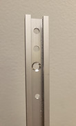
Cutting with Jigs

I needed to cut the front crossbar and the rails I added to the sides. The problem was all I had was a hacksaw and a circular saw and I needed the cuts to be pretty precise. Without access to something like a chop saw or table saw, I didn't have a way to make a repeatable, straight, and precise cut.
I came across a metal-cutting blade for a circular saw, so I decided to make some jigs that would allow me to make repeatable cuts.
The jigs had a guide for the saw to make a straight cut, provided the spacing so the cut would automatically be exactly where I needed it, and had edges to keep the rails aligned. I tapped the end of the rails so I could bolt them to the jigs.
I used a variety of 2x4s to get everything clamped where I needed on the table.
The end result was satisfactory. The rail I cut twice ended up being 1.5mm short in total, making my cuts about 0.75mm off from where I wanted, with the other rails having similar results.
I am perfectly happy with this, given my setup.
3D Printing
I designed brackets for the front crossbar, Z stop bolt, and control board. Additionally, I printed jigs for the cutting and drilling I needed to do. I was very happy with the results of these prints.
I 3D printed them out of PETG (before I disassembled the printer) for the material's strength.
Since I relocated the control screen, I also printed new a case for it that I can mount where I want.


Assembly
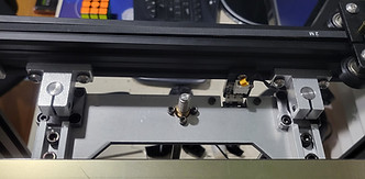
Buildplate Carriage
Consisting of linear bearings, lead screw nuts, rail mounts for the printbed, and the Z stop, the buildplate carriage was the main assembly when it came to putting everything together.
I was very satisfied to see everything come together as it should. The corners of the bearing plates were flush with those of the bearing flanges, the eight holes I drilled using the printed jigs all lined up with the laser-cut ones, and the 24 holes I tapped by hand threaded nicely.
The buildpate fit nicely into the drilled holes on the rails and the assembled carriage perfectly slid onto the threaded rods and guide rods on both sides of the printer.

Z Axis

Both Z axis assemblies consisted of hardened steel guide rods and their mounting brackets, a lead screw connected to a stepper motor with a plum coupler, and a 3D printed mount for the Z stop screw (only on one side). The rods guide the linear bearings attached to the carriage and the stepper mounts to the frame with its laser-cut bracket.
I chose to swap out the stock rigid coupler for a plum coupler to aid with any minor alignment issues that may arise in the lead screw. This is a common upgrade in printers anyway to combat print issues in the Z axis. Alignment looks good either way, but it doesn't hurt.
Not mentioned in the manufacturing section, I cut the hardened steel guide rods to length with an angle grinder, which was cool.
I coated the lead screws in CeramicSpeed UFO Drip simply because I could.
General Fastening
I used t-nuts to secure the majority of components to the frame rails to provide a bit of freedom and to avoid the countless amount of drilling I would otherwise have to do.
When planning everything out, I decided to use sliding t-nuts to increase their contact area in parts like brackets holding frame parts together. I used drop-in t-nuts for less load-bearing parts, but during assembly, it seemed like the drop-in kind would have been sufficient everywhere, which would have simplified assembly quite a bit.
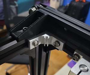
I purchased open-gusset brackets to mount the front crossbar and the side ones I added. This was a great alternative to my original plan to design and laser cut new pulley brackets that would incorporate this, and it doesn't look all that bad either.
I was able to reuse the silver brackets the front crossbar originally used, and 3D printed 20x40mm open gusset brackets that I think look nice.

Results
Leveling and Print Quality
The main purpose of this whole project was to make prints more consistent across the buildplate. Immediately, I noticed leveling the printbed was easier. After a number of prints of different shapes and sizes, and in different locations on the printbed, it looks like prints are coming out well.
With all of these modifications to the Z axis, I was worried about print quality problems such as Z banding, and inconsistent layer heights, but I haven't noticed any problems yet.
Experience Gained
This entire project was practice in taking a project from concept through design, planning, purchasing, manufacturing, and assembly. I worked within the constraints already present in the printer's frame and with ones I set myself to make a product.
I spent a lot of time filling out a BOM when I was looking at what parts to buy. This was very useful at all points of the process and will serve as a good reference in the future.
I had to get creative with my cutting and drilling, as I didn't have the ideal tools, so making jigs and figuring out setups was good practical experience gained.

Final Thoughts
I had a good time with this project and I'm very happy with the result. It was satisfying to have accomplished the upgrade with my own design, which I believe is superior to what's out there already, and I look forward to using it for my future projects.
Market Potential
This is a relatively popular upgrade in the Ender 5 community, so kits and custom dual Z mods are everywhere, My design is a bit more intensive than these other mods, but I believe its improved print visibility and looks, all done while maintaining overall volume, make it a desirable alternative.
Kits can be purchased starting at around $70. The more expensive kits use nicer laser-cut parts and possibly better bearings and motors. There are no fundamental differences in functionality or design. My design uses similar parts, just differently. Additional costs would come from extra open gusset brackets, printed brackets, a new front crossbar, shorter guide rods, and fasteners. Buyers could have the option to print their own brackets for the control board (and be provided the STL) and cut their preexisting rods and crossbeam, bringing the cost of the entire kit right down to that of any other kit. Buyers would have to be open to dedicating slightly more time and effort but in my experience, people doing this type of upgrade would be up for the task.
I currently have no interest in trying to mass produce this to any degree, but I believe it would have the potential to rival what's out there already,


